
If you've ever received an oil analysis report and seen a result like 18/16/13, you've encountered an ISO cleanliness code. It's the standard language for describing how much solid particulate is in a hydraulic or lubrication fluid, and it's the number most component manufacturers reference in their warranty conditions.
The code itself is simple once you know how to read it. The interpretation is where most people go wrong.
This guide covers what the three numbers mean, how to read the range table, what the code doesn't tell you, and what to do when a result comes back outside your target.
Which standard applies
Fluid cleanliness coding is defined by ISO 4406. The current edition is ISO 4406:2021, which supersedes the widely quoted 1999 revision. The coding structure is unchanged; the principal update is that Particle Contamination Monitors (PCMs) are now recognised alongside automatic particle counters and microscopic counting as a means of determining the code.
You will still see reports and OEM specifications citing ISO 4406:1999. They are compatible — but if you are writing a specification, cite the current edition.
What the three numbers mean
The code takes the form XX/YY/ZZ, and each number relates to a particle size threshold measured per millilitre of fluid:
| Position | Particle size | Counts |
|---|---|---|
| First | ≥ 4 µm(c) | All particles 4 µm and larger |
| Second | ≥ 6 µm(c) | All particles 6 µm and larger |
| Third | ≥ 14 µm(c) | All particles 14 µm and larger |
Two points that are routinely misunderstood:
The counts are cumulative
A particle measuring 20 µm is counted in all three numbers, not just the third. Each figure includes everything at that size and above.
The "(c)" notation matters
It indicates the particle counter was calibrated to ISO 11171 using NIST SRM 2806 reference material. This replaced the older ACFTD calibration, and the two are not directly interchangeable. If you are comparing against historical data, the rough equivalence is:
- Old ≥ 5 µm ≈ new ≥ 6 µm(c)
- Old ≥ 15 µm ≈ new ≥ 14 µm(c)
Older two-number codes (for example 16/13) are reported against 5 µm and 15 µm only. They are still in circulation, and they are not the same measurement as a modern three-number code.
Each number is a range, not a count
The code numbers are range codes, not particle counts. A "16" does not mean sixteen particles, or 16,000. It means the count fell somewhere within a defined band.
Each range code represents roughly double the particle count of the one below it.
| Range code | Particles per ml (more than) | Up to and including |
|---|---|---|
| 24 | 80,000 | 160,000 |
| 23 | 40,000 | 80,000 |
| 22 | 20,000 | 40,000 |
| 21 | 10,000 | 20,000 |
| 20 | 5,000 | 10,000 |
| 19 | 2,500 | 5,000 |
| 18 | 1,300 | 2,500 |
| 17 | 640 | 1,300 |
| 16 | 320 | 640 |
| 15 | 160 | 320 |
| 14 | 80 | 160 |
| 13 | 40 | 80 |
| 12 | 20 | 40 |
| 11 | 10 | 20 |
| 10 | 5 | 10 |
| 9 | 2.5 | 5 |
| 8 | 1.3 | 2.5 |
| 7 | 0.64 | 1.3 |
| 6 | 0.32 | 0.64 |
Worked example
A result of 18/16/13 reads as:
- 18 — between 1,300 and 2,500 particles ≥ 4 µm(c) per ml
- 16 — between 320 and 640 particles ≥ 6 µm(c) per ml
- 13 — between 40 and 80 particles ≥ 14 µm(c) per ml
Because the scale is logarithmic, small movements in the code represent large movements in contamination. Compare two samples:
- Sample A: 18/16/13
- Sample B: 21/18/15
Sample B is three range codes higher at 4 µm(c). Three steps is 2 × 2 × 2, so Sample B carries in the order of eight times the particle count at that size. At 6 µm(c) it is two steps, or roughly four times. A code that has drifted "only two or three numbers" is not a minor change.
One caveat: because each code is a band, the true ratio between two samples can vary either side of that figure. Codes are excellent for trending and for specifying targets. They are not precise arithmetic.
Why the smaller sizes matter most
There is a persistent assumption that large particles do the damage and small particles are a background nuisance. In wear terms it is generally the reverse.
The dynamic clearances inside hydraulic components are small — commonly in the range of 0.5 to 5 µm for piston and vane pump elements and servo valve spools. Particles in the 4–6 µm band are the ones that fit those clearances, remain in circulation, and abrade the surfaces that define them. That abrasion generates more particles, which is why contamination tends to accelerate rather than plateau.
- ≥ 4 and ≥ 6 µm(c): the clearance-sized silt responsible for most progressive abrasive wear, loss of volumetric efficiency, valve stiction and silt lock.
- ≥ 14 µm(c): far fewer in number, but individually capable of jamming a spool, scoring a bore or blocking an orifice. This is your indicator of sudden events — a failed component, a breached seal, ingress during maintenance.
Read the first two numbers as your wear rate. Read the third as your risk of an unplanned stoppage.
Setting a target cleanliness code
Target codes are set by the most contamination-sensitive component in the filtered circuit, not by the system average. Sensitivity also tightens as operating pressure rises — the same pump specified for 350 bar will demand a cleaner fluid than at 140 bar.
Indicative targets:
| Component | Typical target |
|---|---|
| Servo and high-response proportional valves | 16/14/11 or cleaner |
| Piston and vane pumps (high pressure) | 17/15/12 |
| Piston and vane pumps (general duty) | 18/16/13 |
| Gear pumps, general industrial hydraulics | 19/17/14 |
| Gearboxes and bearing lubrication | 19/17/14 |
Treat these as a starting point only. The OEM specification governs, and in most cases it is also the warranty condition. Where one sensitive component sits on a shared reservoir, either lift the whole system to that target or give the component dedicated filtration.
What the code does not tell you
An ISO 4406 code covers solid particulate only. A clean code is not a clean bill of health.
- Water is reported separately, in ppm, typically by Karl Fischer titration (ISO 12937). Free and emulsified water degrades additives, promotes corrosion and reduces film strength — none of which shows in the code.
- Varnish — the soluble and sub-micron products of oil oxidation — is not captured by particle counting, and is not removed by conventional filtration or flushing. It requires purpose-specific media or electrostatic treatment.
- Additive depletion, viscosity shift and acid number all require separate analysis.
Getting a result you can trust
Poor sampling produces misleading codes more often than poor filtration does. Before you act on a number, confirm how it was obtained:
- Sample from a live, operating system at normal temperature, from a turbulent line — not from a settled reservoir or a drain point.
- Sample downstream of components and upstream of filters, so you capture what the system is actually generating.
- Flush the sampling port thoroughly before drawing the sample.
- Use clean, certified sample bottles and consistent technique. Trend data is only valid if the method is constant.
Note also that new oil is not clean oil. Fluid delivered in drums and IBCs is routinely dirtier than the target code for the system it is going into. Filter on transfer.
A note on inline particle counters
Permanently installed particle counters give continuous visibility and catch contamination events between scheduled samples. Most work by light extinction (light blockage) or laser scattering.
Be aware of one limitation: these instruments detect anything that interrupts the light path, which includes free water droplets and entrained air bubbles. A sudden spike is worth investigating, but confirm it against a laboratory sample before assuming a particulate ingress event.
Acting on an out-of-target result
If the code sits above your target, work through the following:
- Confirm the result. Re-sample using correct technique before committing to any intervention.
- Review filter selection. Efficiency is expressed as a beta ratio to ISO 16889 — β200(c) equates to 99.5% capture at the stated size, β1000(c) to 99.9%. Specify by beta ratio at a stated micron size, not by nominal micron rating alone.
- Add offline (kidney loop) filtration. Full-flow filters are sized for the flow, not for cleanup. An offline loop polishes the reservoir continuously and can pull a system down several range codes without taking it out of service.
- Check the breathers. A desiccant or particulate-rated breather is the cheapest contamination control on the machine, and a failed one undoes everything downstream.
- Control ingress at the interfaces. Rod seals, filtered fill points, quick-connect couplings and top-up practice are where most avoidable contamination enters.
- Trend, don't spot-check. A single code tells you where you are. A trend tells you where you're heading, and gives you time to act.
Common sources of contamination
- Built-in — residue from manufacture, assembly and installation, if the system was not flushed at commissioning.
- Ingress — through breathers, cylinder rod seals, worn couplings, and during top-ups and maintenance.
- Internally generated — wear debris from the components themselves, which is why contamination accelerates once it starts.
- Introduced — new fluid transferred without filtration, or decanted through contaminated containers.
Summary
- ISO 4406:2021 is the current standard; codes are quoted at 4, 6 and 14 µm(c).
- Each number is a range code, and counts are cumulative.
- Each single step up roughly doubles the particle count.
- The 4 and 6 µm figures drive wear rate; the 14 µm figure signals acute risk.
- Set targets from the most sensitive component and the OEM specification.
- The code covers particulate only — water and oil condition need separate analysis.
- Sampling method determines whether the number means anything at all.
If you need help interpreting an oil analysis report, setting a target cleanliness code for your system, or specifying filtration to reach it, contact our team — or browse our range of hydraulic filters, breathers and offline filtration units.
The Role of Particle Counters in Fluid Analysis
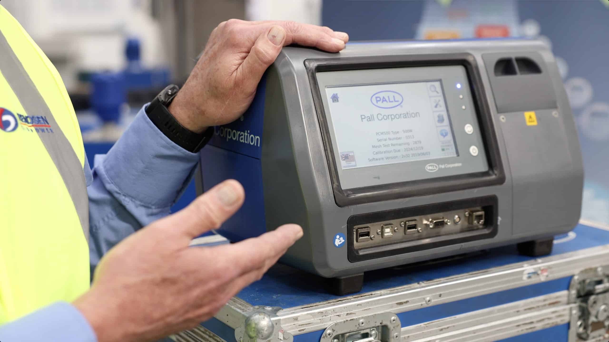
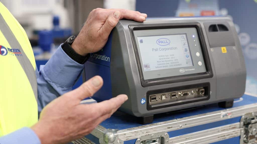
Modern hydraulic systems often employ real-time particle counters to provide continuous cleanliness monitoring. These devices measure particle counts using light blockage or laser techniques and immediately alert operators to contamination spikes.
Conclusion: Clean Fluid Means Reliable Performance
Understanding ISO cleanliness codes isn’t just an academic exercise; it’s a practical tool for proactive maintenance. By regularly testing fluid cleanliness, interpreting results correctly, and taking corrective action when needed, you can:
- Extend equipment life
- Reduce unplanned downtime
- Optimise hydraulic system performance
If you need help interpreting your oil analysis results or want to discuss filtration upgrades, contact us today.
Clean fluid isn’t just a best practice - it’s the key to keeping your operation running smoothly.